
j.c.f.'s Overclocked Athlon.
Last Updated 3/24/00.
Hits since 12/4/99:

So AMD go ahead and build their K7, only it's not a K7, it's an Athlon (oh) and actually not only close the gap on Intel's Pentium III (as it was then before they shrunk it's die using a 0.18 micron process instead of 0.25), but on many benchmarks actually beat the thing! I'm like, go baby! And then the competition on the home front for the machine gets a little tense, what with teenage girl game playing and significant other paper writing and it's time to build the second home machine. By this time I've got xDSL so networking the buggers is not a big deal anymore and then there's this little matter of the unlocked multiplier on the Athlon, sign me up baby!
Kyrotec are out there pushing Athlons to 800MHz and beyond so I figure hey, a couple of MECI TECs (as per the Celery overclock) and a really big fan and a 500MHz Athlon should be good for 750MHz, the golden 50% overclock. Not bad, $200 for a CPU that's faster than (or by the time it was actually built it was as fast as, never buy anything from Computer-X-Press, they're incompetant) anything else currently being sold that's built to operate without a refrigerator.
The Theory.
If you check the specs out on the Athlon it's going to be dumping about 50W at 700Mhz, wow, so I figure if I'm going to be jacking the voltage up and adding another 50MHz to that I'm looking at dumping some serious heat here. Hence a couple of TECs. But there's a bright side to all this current going to drive the TECs, the Athlon sucks juice like it's going out of fashion and then there's the supposed FIC SD-11 mother board's additional finicky nature (the one I'll be using), there's almost nothing like too much power supply current on the 5V and 3.3V rails. Well the TECs become current shunts if run between the 12V and 5V rails for a potential difference of 7V, my prefered way of running the TECs anyway, pumping another 4 to 6 amps or so into the 5V rail, should be gravy. If the TECs need it I can always crack open the power supply and buss out the 3.3V rail which gives 8.7V on the TECs and boosts the current available on the 3.3V rail directly.
The Practice.
So when my new power supply and case eventually show up I'm all a sweat as to exactly which power supply the jerks at Computer-X-Press have shipped me, they couldn't tell me what it was, oh no sir, it's a 'generic' 300W power supply. Well if you check the Athlon page out not all 300W power supplies are equal, some have more current on the 5V and 3.3V rails than others and you need 150W according to AMD, but these guys can't tell me so I'm punting here. Anyway, the supply shows up, and guess what? It's not a stinking 300W supply at all, it's a 235W POWERMAN FPS235-60GT. I tell you, I was ready to nuke these freaks. So they're shipping me another but until then I'm supposed to just sit idly by? When it took over month for the first order to get here? No sir, I pull out the calc. and just see what this power supply is made of, and much to my surprise, it adds up to something like 156W on the 5V and 3.3V rail. Power On!
Next we have to crack the ol' Athlon (actually this happened weeks beforehand, it came from a different vendor). Rumor had it that AMD was having trouble meeting the demand for 500MHz parts and sure enough my Athlon was delayed (a little bit, it still came in weeks before the other stuff) and if a chip fabricator has trouble meeting demand for a slower device in time honored tradition they simply sell a fast part as the slower part. Here's the silicon I got:
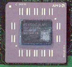
K7650, smokin'! Kinda takes the fun out of it really, 800MHz is likely to be as fast as the 0.25 micron silicon is going to go and that only makes it a 23% overclock, probably don't even need the TECs for that. Oh well, I guess I'll get over it :)
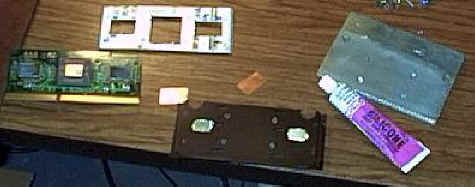
On with the construction then, or at least the parts first. Parts to begin with:
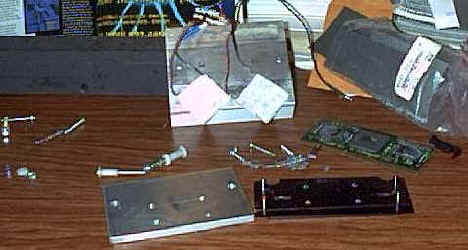
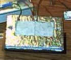
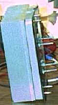
If you thought the cold plate from the celery overclock was big, it's only a puppy compared to this beast. It's actually about a 1/2" taller than it needs to be incase I had to offset the heatsink above the motherboard, turns out by a little surgery on the fan I was fine and if the cold plate is covered with insulation anyway it shouldn't hurt too much. I chose to use the hot plate of the Athlon to hold the SECC, not only because it has pins and holes in all the right places (once you've knocked out the inner four posts anyway) but because they also had nice little risers (or so I thought) for the cache chips:
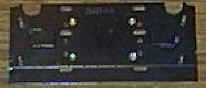
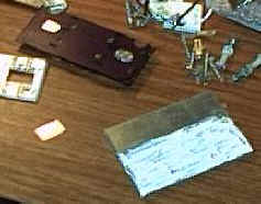
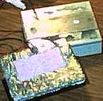
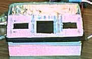
The two semi-circular holes in the top are to make room for the bolts that sandwich the TECs and hold the cold plate to the heatsink. The inner four posts have been removed and their holes widened to allow the bolts that will hold the CPU in place through, I didn't relish the notion of using the original CPU spring faster scheme, that's a once off kind of affair (and, no, I don't just assemble this kind of rig once). Those nice little risers for the cache? Not! AMD was happy with a huge gob of thermal goop, me I found some nice .020" thick copper plate and some 1/16" aluminum plate to fill the indentations on the other side of the original hot plate:
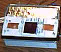
The 1/16" aluminum is just a little bit too think, not by much more than a couple of thou. though so I let it ride, thermal goop and a bit of flex in the plate can take that up. So how to hold them nice little copper shims in place then? Enter the egg carton styrofoam again, only this time much more artfully sculpted:
The foam not only holds the copper shims in place on top of the cache ships but serves to displace as much air out of there as possible -- like we'll be getting to below abmient air temperature and therefore facing the condensation problems, not likely with a >50W heat source in there. That piece of foam actually got sculpted quite a bit more than that, there are several capacitors on the SECC that have to have hollows made for them and the overclocking jig connector also needed some foam removed. Also shown are the aluminim shims in place filling in the indentations on the other side of the original hot plate (now becoming part of the cold plate).
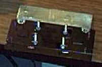
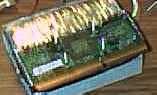
Next we bolt the two plates together, plenty of thermal goop (although not thick you'll note). Note that the other side of that cold plate has the extremely counter sunk receptacles for the CPU bolts, the TECs will be mating with the other face of that and you sure don't want a little steel bolt poking up in there, it'd shatter the TEC:
There are going to be two sets of nuts here, one set to hold the plates together and then a second set later to put tension on the springs holding the CPU to the cold plate. Here's the first set in place with a good dose of locktight, if those loosen up the whole rig has to be disassembled:
Instead of using the MECI plastic TEC housing I figured that sticking the ACE plumbing insulation I use to the cold plate everywhere except where the TECs were to go would do a good job of stopping the TECs from slipping to where they were not supposed to be. Here's the other side of the cold plate, you can see the two CPU mounting bolt heads, soon to be buried in yet more thermal goop:
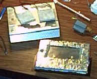
Thermal goop applied and TECs in place on the cold plate:
The MECI heatsink has holes in it where the TECs are now going to be mating with it so fill them up with more thermal goop:
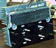
Heatsink now bolted to cold plate:
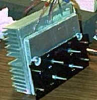
Notice how the nylon insulated bolts holding the cold plate to the heatsink are recessed into the original hot plate. For details of that assembly see the Celeron Overclock, the only difference is that this time the springs go on the heatsink side.
Now we've got the Ace self adhesive pipe insulation stuck over the remaining exposed bits of the cold plate (at least the ones that we can cover up, others must be left uncovered otherwise you'd never get it into the SECC housing on the mother board):
Another strip around the edges and underneath:.
All the insulation around the edges near the exposed cold plate has been stripped of it's outer layer of aluminum, don't want to provide a path for a thermal short. In order to get that outer strip to stick I later resorted to two enourmous cable ties running around the edge.
Foam in place:
Thermal goop and copper shims in place:
CPU in place:
The CPU shouldn't have to compress the foam in order to mate nicely with the cold plate, if it does then take the CPU off and carve out the offending bit of foam, you can usually see an impression in the foam's surface where it needs carving. I chose to use the Athlon's original spring assembly, it only needed a little drilling out and it puts pressure right where it's needed:

Those nuts gets more lock tight, not much stops them from spinning as I have put washers between the nuts and the springs.
I did mention I was using a larger fan didn't I?
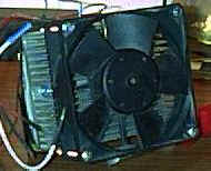
Actually that much of a fan is probably overkill, it was actually jammed by a wire and left that way over night when the CPU was running at 500MHz, I was even playing Unreal Tournament for an hour, sheesh. I don't mind using the big fan however, it happens to be a very quiet fan (I suspect on account of a resistor that is in series with it).
And then I go plug the thing into the FIC SD-11 just to see how it fits before the case came and oops:
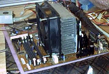
That little white blob under the fan is the ATX power supply connector. Hmmm, guess I'm gonna be doing a little fan remodelling here:
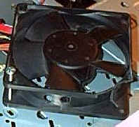
Sans a corner and complete with a couple of blow holes for the chipset she's ready. Doesn't look quite as neat as I intended though, too bad:
This is the first incarnation of the over clocking jig I built from Tom's page:
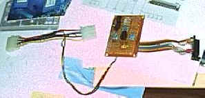
If you try and build one of these with a connector that doesn't have a 90o bend in it I thoroughly recommend chopping up a bit of 1/16" aluminum and plugging it into the connector to act as a heatsink when soldering to those stupid little 0.05" spacing connectors. Here it is all but done:
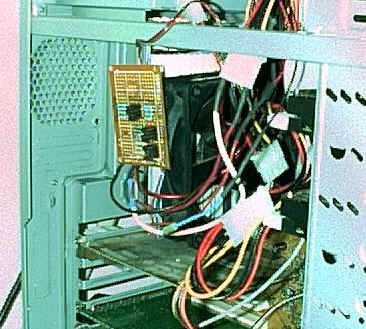
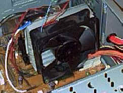
The overclocking jig is held on with a strip of velco stuck to the fan and each TEC is on a separate connector to the power supply, two on one connector might be a little much, better safe than sorry anyway. That overclocking jig basically sucked, I used larger resistors that the Tom's schematic called for and the connector used in that picture doesn't make good contact with the Athlon's test connector, not only that but it is easy to screw up plugging it on and so bend the fingers in the connector, it is almost useless. I did however chance onto one setting that produced a good result, 700MHz. As it is 700MHz is almost stupid fast, alomost fast enough to make Ultima IX playable with my TNT video card. As an aside, what a crying shame of a game, if Origin had made the 3D engine run on anything but the fastest damned machine on the planet with the latest 3dfx card it would be the game of the year bar none, as it is the poor jerks like me sucked into it have to put up with a slide show, well I would if I didn't have a 700MHz CPU but it's not good, believe me.
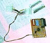
So I go and build another jig with 56 ohm 1/2 watt (for VID and FID at 5V and 3.3V respectively) and 1/4 watt (for BP_FID at 1.6V) resistors and with the lovely AMP connector that pries apart in a rather lovely fashion you can actually mount the connector on the PCB:
And what do I get when I fire the sucker up? Identical, I mean i@#$%ingdentical results as the last jig. So I sit down and try all the combinations and find that BP_FID2 and BP_FID3 are reversed. So either I'm suddenly suffering from some amazing malady only affecting those two connections and am unable to distinguish just those pins or Tom's schematic is wrong. I don't care, I got it going at last.
So how fast does it go now? Not a whole lot faster, 750MHz @ 1.6V is about the limit of my setup, 800 results in a badly corrupted POST, graphics and characters all over the place, urgh. So I figure, maybe the 235W POWERMAN supply is finally running up against it's limits so I slap the L&C 300W supply in there. Well, that was a mistake, that supply is a piece of junk. You can't run TECs between the 12V and 5V rails, so it's either 5V or 12V and at 12V even that 120cfm fan has trouble dumping the heat. Not only that, but I can't even POST at 750MHz (meaning it's not likely to be a heat issue) which confirms my theory about the supply being taxed, here's a clear case of one power supply making 750MHz and the other not. So out it came and back in went the 235W POWERMAN FPS235-60GT, maybe because I can boost the current of the 5V rail or what I dunno, but at least I can hit a rock solid 750MHz with the limiting resistor on the fan bypassed (summer of course will be another thing but that's months away).
All attempts to up the voltage lead to more complete failures (no video, nada) so more research is probably in order there to find out if the settings are doing what they should be or whether the supply is crapping out or what, but in any event given the clear thermal situation I can't be expecting to up many settings and it's difficult to be unhappy with the golden 50% overclock even if it is technically only 15%.
Perhaps the TECs are at their limit, my calculations certainly indicate that I am pushing them so if I get really enthusiastic I'll try just a plain ol' heatsink, but then I loose the current shunt and I should probably get a temperature probe so I can add a bit of science to this whole affair. Ah, the life of the overclocker is never complete...
It's been a few months and the rig has been refined and reworked a few times now, for the next installment please see the Athlon Overclock Phase II.
Should you really want to communicate you can eMail to:
jforster@someplace.spam.dont.go
The Top.