Aum

j.c.f.'s Atlhon Overclock Phase II.


Last Updated 3/27/00.
Hits since 12/4/99:


      Nothing in the world of overclocking is ever complete, my overclocks especially.    Here then is the continuing saga of my Athlon overclocking.


The Theory.

      After the Tech Zone published my first article I got a bunch of feedback, some of it quite useful.    Amongst the most often pointed out things were that (a) TECs really were overkill for such a project and that (b) the reason I couldn't push my Athlon 500 past 750 was because the cache was the limiting factor and it's divider needed to be changed.

The Practice.

      So some time ago I for reasons I don't quite recall but that may have had a lot to do with boredom, you know, the "OC'd system that's stable enough to be boring needs more tweaking syndrome", I assembled the rig without the TECs and sure enough things still ran.    Wanting to add a little science to my madness I went out and bought a Radio Shack Precision Indoor/Outdoor Thermometer so I could get some actual measurements of how effective my various cooling strategies were:

thermal feedback device

   A bit of work with a mill bastard file and it's probe is slim enough to give me a good read of the temperature of the cold plate (or heatsink if I'm not using the TECs).    I don't really care about CPU temperature, when using TECs on a CPU that isn't swaddled in insulation the one thing you care about is not letting the temperature of the cold plate drop below ambient room temperature, no condensation please thankyou very much.    Of course, being the daft twit I am I bought the thermometer after removing the TECs so I don't have data on how well the old rig was doing, some days you just burn bridges I guess, although having assembled the new system the bolts on the back of the CPU feel much colder than they used to so it's a good bet things are dramatically improved.
      The cool part about getting the Indoor/Outdoor thermometer is that you can get a reading of the ambient room temperature easily, flick the switch and wait a few seconds, very convenient.    Temperatures running at 750Mhz @ 1.6V without the TECs were typically 27 degrees F over ambient air temperatures near the case, not too bad, and while gaming another 4 to 6 degrees warmer still.    No sweat if you live in an air conditioned apartment in Manhattan, I however happen to live in a swamp cooled house (evaporative cooling) in Tucson and while they say "but it's a dry heat" they're not talking about August.    I'll grant you, while it's not like the Deep South, 99 degrees F and 99% Relative Humidity we are talking about 50% RH and over which tends to kick most swamp coolers in the butt -- meaning I get indoor temperatures pushing 90 degrees F under the worst conditions.    So that's 90 + 27 + 6, ouch, 123 degrees!    Yikes, an awful lot of silicon tends to list 120 as the upper limit on operating conditions.    And that 123 degrees is not counting the fact that since installing the thermometer I notice that the temperature right next to the computer tends to be about 10 degrees warmer than the rest of the house, might have something to do with the 19" monitor and the DSL router and a computer sinking enough juice for two normal machines.    Summons TECs.

      But summer was still months away so I went on using my system as it was without any active cooling, however I was noticing a disturbing situation that would arise on my machine.    Periodically the system would just get plain durn persnickety.    It had nothing to do with temperature, application or even OC'd speed as I found when I drug the machine down to 650MHz for a while.    Symptoms could include a game crashing and upon starting the game again another identical crash to BSODs from things like the IFS system (part of the networking).    But only once in a couple of weeks and once it happened it seemed the machine stayed that way for a number of minutes, usually by the third reboot it's off and running happy as Larry again.    So I'm starting to think those cache chips are freaky, it's not a case of pushing them just a little bit too hard, its a case of push them over spec. (be it a little or a lot) and some time or other they're gonna screw up.    So I fire up H. Oda's wondrous WCPUA2 and set the cache to 1/3, and sure enough, problems are gone.    Well, cool, I can live with a point and click or two on system startup and believe me, if you've never looked at the resistors that need moving to permanently strap the cache divider WCPUA2 looks real appealing.    At least until March rolled around and we discover that he's put a time limit in the stinking thing, %$%#*!    Fine, so you set the date back to February, use WCPUA2 and then set it back again, oh, and then we want to install a new video card with the concomitant multiple reboots getting drivers into line, eyes soldering iron and magnifying lens...


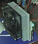
      So I'll skip most of the construction then, mostly because I reassembled the rig with TECs in an afternoon in a bit of a rush and didn't have time to snap pics and also because most of it is the same sort of thing as the first time around.    What did change was the heatsink, while the MECI heatsink is a wonderful brute, it's designed for convection cooling, it doesn't get the same kind of a benefit from a fan that a heatsink designed for fan forced air flow does.    So I got a couple of the Plycon Ultimate Alpha Heatsinks and used them vertically side by side instead:

heatsinks

      An added benefit of using these heatsinks is that they are a bit longer (taller the way I use them) and have a completely flat back (you can only mount stuff in the dead center of the MECI heatsinks) so I can offset them and give that 5 1/4" muffin fan a bit of room so it doesn't hit the power supply connector:

front side quarter

front side quarter

      Actually that's another 5 1/4" muffin fan, I ditched the old one that had the corner chopped out of it and ripped another one out of the last old AT&T lying around the place:

front side quarter

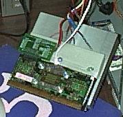
      From behind you can see the white probe of the thermometer jammed in there:

behind

      You can also see that I'm not using the overclocking jig I built for the last rig, that one's at work overclocking my Athlon there, at home I use the one from K7OC as tom was so kind to have sent me an evaluation unit after the Tech Zone published my first article, hey I got something tangible back for my writing efforts, who'd da thunk it?    It's actually a pretty slick unit with a silk screen on the back of it with the switch settings, very handy.

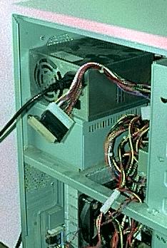
      Another thing that changed was the source of current to run the TECs with, I wanted a bit more than 7V across the TECs and even given 300W power supplies it's still asking a lot to expect it to drive two TECs and an 800MHz Athlon as well:

extra power supply

      Of course you can't just use an ATX supply as is, you have to strap the supply up so it will turn on at all and you also have to load up the 5V rail a bit otherwise it won't stay on.
ATX 20 pin power connector
 Pin#     Pin#
------------------------
| 3.3V  11       1* 3.3V |
| -12V  12       2  3.3V |
|  COM  13*(Gnd) 3  COM  |
| PS-ON 14*      4  +5V  |
|  COM  15       5  COM  |
|  COM  16       6  +5V  |
|  COM  17       7  COM  |
|  -5V  18       8  PW-OK|
|  +5V  19       9  5VSB |
|  +5V  20      10  +12V |
------------------------
      I use an old power supply connector off a dead ATX mother board (heat guns are marvelous devices) with pins 13 and 14 connected to get it to turn on a 10 ohm resistor across pins 5 and 6 for the load.    It's all wrapped up in black electrical tape so the photo doesn't show too much:

old ps connector

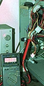
      I can hear the cognoscenti going "only 10 ohms?"    As others have noted, you need at least a 2 amp load on the 5V rail before you get 12V out of the 12V rail, with my 0.5A load I only get about 9.3V, and therein lies the beauty of the whole arrangement.    You'll remember that I noted earlier on that my aim is to keep the cold plate just above ambient room temperature as I'm not about to fully insulate the thing to prevent condensation from forming -- which isn't to say that I don't have a can of expanding latex insulation laying around the place incase I get carried away one day, it's just not today.    Nor is that to say that the cold plate doesn't have insulation stuck to it, it does so the TECs aren't pumping ambient air heat around for no good purpose, it's the CPU that hasn't got insulation, to do that involves major structural changes to my rig.    Traditionally you either need a variable supply and or a variable fan speed control to be able to choose your cold plate temperature, the variable supply being pretty durn expensive.    Here, by adding or removing resistors across the 5V rail you can have your variable supply for the cost of a regular PC power supply.    For instance, if I stick another 8.2 ohm load in there the voltage jumps up to 10.2V, fans speed up, TECs start working harder and the cold plate temperature starts going down.    As it is with the Athlon running at 800MHz @ 1.6V at idle (that's just no use, not sleeping, if it slept then there would be puddles shortly followed by ice) the cold plate temperature is 10 degrees F over ambient room temperature, if I plug in another two 8.2 ohm resistors taking the total load on the 5V rail down to 2.9 ohms for a 1.7A current the cold plate drops to 5 degrees over ambient room temperature (actually less than the temperature around the case), close enough for me, gaming it's the same 4 to 6 degrees warmer that the passive cooling system observed.

resistors everywhere


      Unfortunately I can't show you much about strapping the cache to 1/3 of the CPU clock, as you've no doubt noticed my camera is a representative of the cheap and nasty bracket and is not even remotely capable of that kind of photography.   About all I can provide is a few hints on technique and the table of resistor placement that I have gleaned from one site or another:
     R103 R104   R106 R107   R110 R111
1/2   O    X      X    O      O    X
1/3   X    O      O    X      O    X
2/5   0    X      O    X      X    O
      X indicates the resistor is present, O absent, ie to get 1/3 you move the resistor from R104 to R103 and the resistor from R106 to R107.
      As far as technique goes, the most off putting thing about this hole affair, the right equipment turned what was an impossible task to a relatively trivial one.    First, get a magnifying lamp or a set of jewelers half eyes, anything so that you can at least get an idea of what you are doing.    Then get a long reach fine tip for your soldering iron, that way you can lay the tip across both ends of a resistor to remove it, apply solder to both ends and the resistor should come away with the soldering iron, that or it's easy enough to scoop it up.    I found that to have an exacto blade in one hand (or lying nearby) to remove the resistor from the tip of the soldering iron was a far superior method to the "flick it off and try and find the resistor" approach.    For soldering the buggers back on I found a pair of locking tweezers to be of great benefit, placing the resistor in the tweezers with one end protruding, after placing a small blob of solder on that end and another on the pad on the CPU all that is required is to hold the resistor in place and touch the soldering iron to the exposed end.    The crucial point is holding the tweezers in such a way as to be able to release them quickly otherwise the torque of you manipulating the tweezers is going to be transferred to that little itty bitty pad and it's more than likely gonna part company with the CPU.


The Results.


      So having the cache strapped to 1/3 means I can POST and successfully boot at 800Mhz and run for as long as I care to without any system glitches, and having the TECs in there pumping their little hearts out means I can have it all year round.    However I can't touch 850, not at any voltage up to and including 1.8V and I'm not game enough to risk my fantastically fast machine just to eek another frame per second out of it, and I do mean frame.    For instance Unreal Tournament on a TNT1 at 800x600 goes from 51.0 fps @750 MHz to 51.9 at 800, no big difference.    Even using the TNT2 at work the bench is the same so we're into diminishing returns territory.

      Another result, this time from changing the heatsinks is the increased effect that high and low fan speeds have on the temperature of the cold plate.    Using plain convention and the old MECI heatsink there is only a few degrees difference between having the 24 ohm resistor in series with the fan or bypassed, with the new heatsinks there's a 15 degree difference!    Might've been more, I panicked and threw the switch when I glanced up and saw the thermomenter over 100 degrees when it had been at 85.    Guess I put up with the increased fan noise.

      Is there anything more to do?    To go at a higher clock speed will mean running the CPU below room temperature (unless I'm missing something here).    I will need to use the 70W TECs I have from Plycon (bought just in case again), I'd have to build a linear supply to drive 'em (which I might do anyway, that could be fun, one less fan in the case at any rate), those puppies are sinking 6A a piece and these ATX supplies are typically only good for 8A on the 12V rail, then I'd have to fully insulate the CPU with all of the structural details involved there.    And to cap it all off I'd probably need a water cooled system to dump the 200W or more of waste heat, I think phase III will be waiting for a while...


Should you really want to communicate you can eMail to: jforster@someplace.spam.dont.go

The Top.