|
|
|
|
|
|
|
|
|
|
|
|
Modular Connector |
||
|
|
CONCEPT |
||
|
|
|
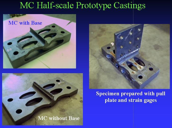
The modular connector (MC) is a cast piece used to connect the beam flange to the column. It is envisioned that typical construction will involve shop-welding the MC to beam flanges and field-bolting the MC to the column flange (See Figure 1).
Figure 1. Location of Modular Connector
The connectors possess a certain level of compliance, thus the joint will be, strictly speaking, semi-rigid. However, high rotational stiffness is achievable, and thus the MC provides a bolted alternative for full-moment connections that eliminates the potential for brittle behavior associated with welding construction. The MC is engineered to deliver reliable and repeatable energy dissipation through improved cyclic ductility. This objective is achieved through the elimination of concentrated plastic strain regions and the reduction in bolt prying forces. The geometry required to produce such outcomes is not necessarily available in the configuration or fastening procedures associated with traditional rolled shapes. Thus, the MC will utilize the versatility afforded by casting processes to obtain optimal geometric configurations.
Figure 2. Deformed Modular Connector under moment at the end of beam
Figure 3. Typical configuration of Modular Connector
CLICK HERE TO SEE ANALYTICAL and EXPERIMENTAL RESULTS
|